12.6. Tweaking Light
Relevant to Blender v2.31
Ok, now you've got the basics. Now we can really talk of light. We will work on a single example, more complex than a plain 'sphere over a plane' setup, to see what we can achieve in realistic lighting with Blender.
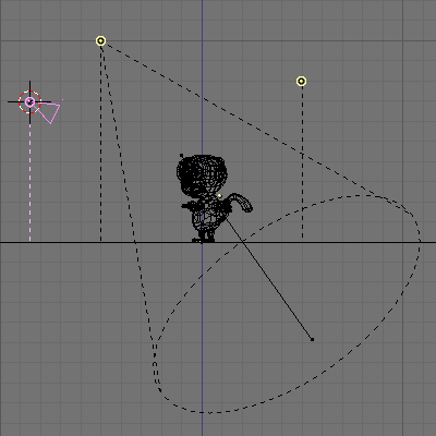
We will resort to the setup in Figure 12-25. The simian figure is Cornelius, Suzanne's baby brother. He has a somewhat shiny light brown material (R=0.8, G=0.704 B=0.584, Ref=0.7, Spec=0.444, Hard=10 - Yes, not very monkey-like, but we are talking of lights, not of materials!) and stands on a blue plane (R=0.275, G=0.5, B=1.0, Ref=0.8, Spec=0.5, Hard=50). For now he's lit by a single spot (Energy=1.0, R=G=B=1.0, SpotSi=45.0, SpotBl=0.15, ClipSta=0.1, ClipEnd=100, Samples=3, Soft=3, Bias=1.0, BufSize=512).

A rendering of Cornelius in this setup, with OSA=8 and Shadows enabled, gives the result in Figure 12-26. The result is ugly. You have very black, unrealistic shadows on Cornelius, and the shadow cast by Cornelius himself is unacceptable.

The first tweak is on ClipSta and ClipEnd, if they are adjusted so as to encompass the scene as tightly as possible (ClipSta=5, ClipEnd=21) the results get definitely better, at least for projected shadow. Cornelius's own shadow is still too dark (Figure 12-27).

To set good values for the Clipping data here is a useful trick: Any object in Blender can act as a Camera in the 3D view. Hence you can select the Spot Light and switch to a view from it by pressing CTRL-NUM0. What you would see, in shaded mode, is shown in Figure 12-28.
All stuff nearer to the Spot than ClipSta and further from the spot than ClipEnd is not shown at all. Hence you can fine tune these values by verifying that all shadow casting objects are visible.
Figure 12-28. Spot Light Clipping tweak. Left: ClipSta too high; Centre: Good; Right: ClipEnd too low.

What is still really lacking is the physical phenomenon of diffusion. A lit body sheds light from itself, hence shadows are not completely black because some light leaks in from neighbouring lit regions.
This light diffusion is correctly accounted for in a Ray Tracer, and in Blender too, via the Radiosity Engine. But there are set-ups which can fake this phenomenon in an acceptable fashion.
We will analyse these, from simplest to more complex.
12.6.1. Three point light
The three point light set-up is a classical, very simple scheme to achieve a scene with softer lighting. Our Spot Light is the main, or Key, Light of the scene, the one casting shadow. We will add two more lights to fake diffusion.
The next light needed is called the Back Light. It is placed behind Cornelius (Figure 12-29). This illuminates the hidden side of our character, and allows us to separate the foreground of our picture from the background, adding an overall sense of depth. Usually the Back Light is as strong as the Key Light, if not stronger. Here we used an Energy 1 Lamp Light (Figure 12-30).


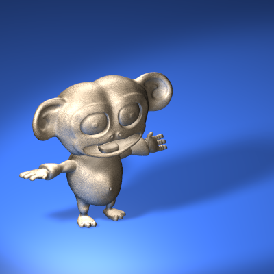
The result is already far better. Finally, the third light is the Fill Light. The Fill light's aim is to light up the shadows on the front of Cornelius. We will place the Fill Light exactly at the location of the camera, with an Energy lower than the lower of Key and Back Lights (Figure 12-31). For this example an Energy=0.75 has been chosen (Figure 12-32).

The Fill light makes visible parts of the model which are completely in darkness with the Key and Back light only.
 | Color leakage |
|---|---|
The three-point set up can be further enhanced with the addition of a fourth light, especially when a bright coloured floor is present, like in this case. If there is a bright coloured floor our eye expects the floor to diffuse part of the light all around, and that some of this light impinges on the model. To fake this effect we place a second spot exactly specular to the Key Light with respect to the floor. This means that - if the floor is horizontal and a z=0, as it is in our example, and the Key light is in point (x=-5, y=-5, z=10), then the floor diffuse light is to be placed in (x=-5, y=-5, z=-10), pointing upward (Figure 12-33). The energy for this light should be lower than that of the Key Light (here it is 0.8) and its colour should match the colour of the floor (here R=0.25, G=0.5, B=1.0). The result is shown in Figure 12-34. Please note that we used a Spot light and not a lamp, so it would be completely blocked by the floor (shadowed) unless we set this spot shadeless by pressing the appropriate button. Indeed we could have used a Lamp but if the floor is shiny the light it sheds is more reflected than diffused. Reflected light, physically is itself a cone coming from the specular source. You can further enhance the effect by making the Spot cast shadows and by setting its ClipStart value high enough so that the plane casts no shadow, or by making it affect only its layer and placing the floor on another layer. |


12.6.2. Three point light - Outdoor
By using a Spot light as a key light the previous method is sadly bound to indoor settings or, at maximum, outdoor settings at night time. This is because the Key light is at a finite distance, its rays spread and the floor is not evenly illuminated.
If we were outdoor on a clear sunny day all the floor would be evenly lit, and shadows would be cast.
To have a uniform illumination all over the floor a Sun light is good. And if we add a Hemi light for faking the light coming from all points of the sky (as in Figure 12-8) we can achieve a nice outdoor light... but we have no shadows!
The setup of the Key light (the Sun, R=1.0, G=0.95, B=0.9, Energy=1.0) and the Fill/Back Light (both represented by the Hemi, R=0.8, G=0.9,B=1.0, Energy=0.4) is shown in Figure 12-35 and the relevant rendering in Figure 12-36


The lack of shadow makes Cornelius appear as if he were floating in space. To have a shadow let's place a Spot coincident with the Sun and with the same direction. Let's make this spot a Shadow Only Spot (with the appropriate button). If Energy is lowered to 0.9 and all other settings are kept at the values used in the previous example (BufSize=512, Samples=3, Soft=3, Bias=1, ClipSta=5, ClipEnd=21) the result is the one of Figure 12-37 (center).

The shadow is a bit blocky because Cornelius has many fine details and the BufSize is too small, and the Samples value is to low to correctly take them into account. If BufSize is raised to 2560, Samples to 6 and Bias to 3.0 the result is the one in Figure 12-37 (right). Much smoother.
12.6.3. Area Light
The concept of Light coming from a point is an approximation. No real world light source is dimensionless. All light is shed by surfaces, not by points.
This has a couple of interesting implications, mainly on shadows:
Sharp shadows do not exist: shadows have blurry edges.
Shadow edge blurriness depends on the relative positions and sizes of the light, the shadow casting object and the object receiving the shadow.
The first of these issues is approximated with the 'Soft' setting of the Spot light, but the second is not. To have a clearer understanding of this point imagine a tall thin pole in the middle of a flat plain illuminated by the Sun.
The Sun is not a point, it has a dimension and, for us Earthlings, it is half of a degree wide. If you look at the shadow you will notice that it is very sharp at the base of the pole and that it grows blurrier as you go toward the shadow of the tip. If the pole is tall and thin enough its shadow will vanish.
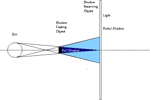
To better grasp this concept have a look at Figure 12-38. The Sun sheds light, the middle object completely obstructs the Sun's rays only in the dark blue region. For a point in the light blue region the Sun is partially visible, hence each of these areas is partially lit.

The light blue region is a partial shadow region where illumination drops smoothly from full light to full shadow. It is also evident, from Figure 12-38 than that this transition region is smaller next to the shadow casting object and grow larger far away from it. Furthermore, if the shadow casting object is smaller than the light casting object (and if the light casting object is the Sun this is often the case) there is a distance beyond which only partial shadow remains Figure 12-39.
In Blender, if we place a single Spot at a fixed distance from a first plane and look at the shadow cast at a second plane as this second plane gets further away we notice that the shadow gets larger but not softer (Figure 12-40).

To fake an area light with Blender we can use several Spots, as if we were sampling the area casting light with a discrete number of point lights.
This can either be achieved by placing several Spots by hand, or by using Blender's DupliVert feature (Section 21.2), which is more efficient.
Add a Mesh Grid 4x4. Where the spot is, be sure normals are pointing down, by letting Blender show the Normals and eventually flipping them, as explained in Section 6.2.2 (Figure 12-41). Parent the Spot to the Grid, select the Grid and in the Object Context Anim Settings Panel (F7) press DupliVert and Rot. Rot is not strictly necessary but will help you in positioning the Area Light later on. You will have a set of Spots as in Figure 12-42.


Then decrease the Energy of the Spot. If for a single Spot you used a certain energy, now you must subdivide that energy among all the duplicates. Here we have 16 spots, so each should be allotted 1/16 of Energy (that is Energy=0.0625).
The same two renderings of above, with this new hacked area light will yield the results in Figure 12-43. The result is far from that expected, because the Spot light sampling of the Area light is too coarse. On the other hand, a finer sampling would yield a higher number of duplicated Spots and to unacceptable rendering times.

A much better result can be attained by softening the spots, that is setting SpotBl=0.45, Sample=12, Soft=24 and Bias=1.5 (Figure 12-44).

Finally, Figure 12-45 shows what happens to Cornelius once the Key Light is substituted with 65 duplicated Spots of Energy=0.0154 in a circular pattern. Please note how the shadow softly goes from sharp next to the feet to softer and softer as it gets further away from him. This is the correct physical behavior.
12.6.4. Global Illumination (and Global Shadowing)
The above techniques work well when there is a single, or at least a finite number of lights, casting distinct shadows.
The only exceptions are the outdoor setting, where the Hemi Light fakes the light cast by the sky, and the Area Light, where multiple spots fake a light source of finite extension.
The first of these two is very close to nice outdoor lighting, were it not for the fact that the Hemi Light casts no shadows and hence you don't have realistic results.
To obtain a really nice outdoor setting, especially for cloudy daylight, you need light coming from all directions of the sky, yet casting shadows!
This can be obtained by applying a technique very similar to the one used for the Area Light setup, but using half a sphere as a parent mesh. This is usually referred to as "Global Illumination".
You can either use a UVsphere or an IcoSphere, the latter has vertices evenly distributed whereas the former has a great concentration of vertices at poles. Using an IcoSphere hence yields a more 'uniform' illumination, all the points of the sky radiating an equal intensity; a UVsphere casts much more light from the pole(s). Personally I recommend the IcoSphere.
Let's prepare a setup, comprising a plane and some solids, as in Figure 12-46. We will use simple shapes to better appreciate the results.

Switch to top view and add an IcoSphere, a subdivision level 2 IcoSphere is usually enough, a level 3 one yields even smoother results. Scale the IcoSphere so that it completely, and loosely, contains the whole scene. Switch to front view and, in EditMode, delete the lower half of the IcoSphere (Figure 12-47). This will be our "Sky Dome" where the spots will be parented and dupliverted.

Again in Top View add a Spot Light, parent it to the half IcoSphere (CTRL-P) and press the DupliVert and Rot buttons exactly as in the previous example. The result, in FrontView, is the one in Figure 12-48.

This is not what we want, since all spots point outwards and the scene is not lit. This is due to the fact that the IcoSphere normals point outward. It is possible to invert their directions by selecting all vertices in Edit Mode and by pressing the Flip Normals button in the Mesh Tools Panel of the Editing (F9) Context (Figure 12-49).

This leads to the new configuration in Figure 12-50.

To obtain good results select the original Spot Light and change its parameters to a wide angle with soft boundaries (SpotSi=70.0; SpotBl=0.5); with suitable ClipSta and ClipEnd values; in this case 5 and 30, respectively, in any case appropriate values to encompass the whole scene; increase samples to 6 and softness to 12. Decrease energy to 0.1; remember you are using many spots, so each must be weak. (Figure 12-51).

Now you can make the rendering. If some materials are given and a world set, the result should be that of Figure 12-52. Note the soft shadows and the 'omnidirectional' lighting. Even better results can be achieved with a level 3 IcoSphere.

This Global Illumination technique effectively substitutes, at a very high computational cost, the Hemi for the above outdoor setting.
It is possible to add a directional light component by faking the Sun either via a single spot or with an Area Light.
An alternative possibility is to make the IcoSphere 'less uniform' by subdividing one of its faces a number of times, as is done for one of the rear faces in Figure 12-53. This is done by selecting one face and pressing the Subdivide button, again in the Mesh Tools Panel of the Editing (F9) Context. Then de-select all, re-select the single inner small face and subdivide it again, and so on.

The result is a very soft directional light together with a global illumination sky dome or, briefly, an anisotropic sky dome (Figure 12-54). This is quite good for cloudy conditions, but not so good for clear sunny days. For really clear days, it is better to keep the sky dome separate from the Sun light, so as to be able to use different colours for each.
