4.6. Editing Context
The Editing Context shows the main EditMode tools and is not divided into Sub-Contexts. It displays two Panels if the Object is not in EditMode. Further Panels are added if the Object is in EditMode, depending on the Object type.
The two Panels which are always present change their buttons according to the Object type anyway, so this reference is subdivided by Object type:
4.6.1. Mesh objects
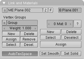
4.6.1.1. Link and Materials Panel
On the first line:
4.6.1.1.1. Mesh Menu
Selects which Mesh DataBlock is linked to this Object.
4.6.1.1.2. ME:
Shows Mesh DataBlock name, allowing for changes.
4.6.1.1.3. F
Fake User button, to keep Mesh DataBlock even if unlinked.
4.6.1.1.4. OB:
Shows Object name, allowing for changes.
Below the first line we can see two groups of buttons, Vertex Groups on the left, Material links to the right.
4.6.1.1.5. Group Menu
Allow for selecting an existing vertex group.
4.6.1.1.6. Group Name
This Text Box shows the current vertex group name, allowing editing.
4.6.1.1.7. Weight
Sets the current vertex group's bone deformation strength.
If the Mesh is in EditMode the following buttons also appear below:
4.6.1.1.8. New
A new group is created.
4.6.1.1.9. Delete
Current group is deleted.
4.6.1.1.10. Assign
Currently selected vertices are added to the current group.
4.6.1.1.11. Group Name
Currently selected vertices are removed from the group.
4.6.1.1.12. Select
Vertices belonging to the group are added to current selection.
4.6.1.1.13. Desel.
Vertices belonging to the group are deselected.
4.6.1.1.14. AutoTexSpace
This option calculates the texture area automatically, after leaving EditMode. You can also specify a texture area yourself (Outside EditMode, in the 3D Window; TKEY), in which case this option is turned OFF.
On the right column:
4.6.1.1.15. 1 Mat 1
This button can be used to specify which Material should be shown, i.e. which Material is active. The first digit indicates the amount of Materials, the second digit indicates the index number of the active Material. Each face in a Mesh has a corresponding number: the 'Material index'. The same is true of Curves and Surfaces.
4.6.1.1.16. ?
In EditMode, this Button indicates what index number, and thus what Material, the selected items have.
4.6.1.1.17. New
Make a new index. The current Material is assigned an extra link. If there was no Material, a new one is created.
4.6.1.1.18. Delete
Delete the current index. The current Material gets one less link. The already used index numbers are modified in the ObData.
4.6.1.1.19. Select
In Edit Mode, every vertex with the current index number is selected.
4.6.1.1.20. Deselect
In Edit Mode, every vertex with the current index number is deselected.
4.6.1.1.21. Assign
In EditMode, the current index number is assigned to the selected vertices.
4.6.1.1.22. Set Smooth
All selected faces are rendered with smoothly varying normals. Edges are not visible.
4.6.1.1.23. Set Solid
All selected faces are rendered with constant normals. Edges are visible.
4.6.1.2. Mesh Panel
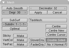
This panels owns two columns of buttons; on the left:
4.6.1.2.1. Auto Smooth
Automatic smooth rendering (not faceted) for meshes. Especially interesting for imported Meshes done in other 3D applications. The Button Set smooth must have been used on faces to make Auto Smooth work. The smoothing isn't displayed in the 3D Window, only in renderings.
4.6.1.2.2. Degr:
Determines the degree in which faces can meet and still get smoothed by Auto Smooth.
4.6.1.2.3. SubSurf
This option turns a Mesh Object into a SubSurfed Mesh, meaning procedural smooth subdivision of Mesh objects.
4.6.1.2.4. Subdiv:
Number of subdivisions for S-Meshes. The neighbouring unlabelled Num Button sets the level of subdivision at Rendering Time. This allows fast editing on coarse SubSurfaced meshes and smooth rendering on fine SubSurfaced meshes.
4.6.1.2.5. Optimal
In EditMode the way of representing the original mesh changes, hiding edges and showing "SubSurfed" edges.
4.6.1.2.6. Sticky: Make/Delete
Blender allows you to assign a texture coordinate to Meshes that are derived from the way the Camera view sees the Mesh. The screen coordinates (only X,Y) are calculated from each vertex and these coordinates are stored in the Mesh. It's as if the texture is permanently projected and fixed on the Mesh as viewed from the Camera; it becomes "sticky". Use "Sticky" to match a 3D object exactly with the Image Texture of a 3D picture. This option also allows you to create special morphing effects. If the image is already "sticky", the button allows you to remove this effect.
4.6.1.2.7. VertCol: Make/Delete
A colour can be specified per vertex. This is required for the VertexPaint option. If the Object DrawType is "Shaded", these colours are copied to the vertex colours. This allows you to achieve a radiosity-like effect (set MaterialButtons->VertCol ON). If the Mesh is "Double Sided", this is automatically turned off.
4.6.1.2.8. TexFac: Make/Delete
Assigns a texture per face. Will be automatically set when you use the UV-Editor to texture a realtime model.
For the right column:
4.6.1.2.9. Decimator
This is present only in Object Mode. It shows the total number of triangular faces of the Mesh (Quads are computed as two tris). You can reduce the number of faces with this Num Button. Faces are joined starting from the most 'coplanar' ones.
The result is shown in the 3D Window.
4.6.1.2.10. Apply, Cancel
If you are satisfied with mesh decimation you can make it permanent, otherwise you can revert to the previous state.
4.6.1.2.11. TexMesh
Enter the name of another Mesh block here to be used as the source for the texture coordinates. Morphing-like effects can then be achieved by distorting the active Mesh. For example, a straight stream of water (as an animated texture) can be placed in a winding river.
4.6.1.2.12. Centre
Each ObData has its own local 3D space. The null point of this space is placed at the Object centre. This option calculates a new, centred null point in the ObData. This may change texture coordinates.
4.6.1.2.13. Centre New
As above, but now the Object is placed in such a way that the ObData appears to remain in the same place.
4.6.1.2.14. Centre Cursor
The new null point of the object is the 3D-Cursor location.
4.6.1.2.15. SlowerDraw, FasterDraw
When leaving EditMode all edges are tested to determine whether they must be displayed as a wire frame. Edges that share two faces with the same normal are never displayed. This increases the recognisability of the Mesh and considerably speeds up drawing. With SlowerDraw and FasterDraw, you can specify that additional or fewer edges must be drawn when you are not in EditMode.
4.6.1.2.16. Double Sided
Only for display in the 3Dwindow; can be used to control whether double-sided faces are drawn. Turn this option OFF if the Object has a negative 'size' value (for example an X-flip).
4.6.1.2.17. No V.Normal Flip
Because Blender normally renders double-sided, the direction of the normal (towards the front or the back) is automatically corrected during rendering. This option turns this automatic correction off, allowing "smooth" rendering with faces that have sharp angles (smaller than 100 degrees). Be sure the face normals are set consistently in the same direction (CTRL-N in EditMode).
4.6.1.3. Mesh Tools Panel
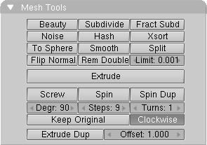
Left to right, and top to bottom:
4.6.1.3.1. Beauty
This is an option for the Subdivide command. It splits the faces into halves lengthwise, converting elongated faces to squares. If the face is smaller than the value of Limit:, it is no longer split in two.
4.6.1.3.2. Subdivide
Selected faces are divided into quarters; all edges are split in half.
4.6.1.3.3. Fract Subd
Fractal Subdivide. Like Subdivide, but now the new vertices are set with a random vector up or down. A requester asks you to specify the amount. Use this to generate landscapes or mountains.
4.6.1.3.4. Noise
Here Textures can be used to move the selected vertices up a specific amount. The local vertex coordinate is used as the texture coordinate. Every Texture type works with this option. For example, the Stucci produce a landscape effect. Or use Images to express this in relief.
4.6.1.3.5. Hash
This makes the sequence of vertices somewhat random.
4.6.1.3.6. Xsort
Sorts the vertices in the X direction. This creates interesting effects with VertexKeys or 'Build Effects' for Halos.
4.6.1.3.7. To Sphere
All selected vertices are blown up into a spherical shape, with the 3DCursor as a midpoint. A requester asks you to specify the factor for this action.
4.6.1.3.8. Smooth
All edges with both vertices selected are shortened. This flattens sharp angles.
4.6.1.3.9. Flip Normals
Toggles the direction of the face normals.
4.6.1.3.10. Rem Doubles
Remove Doubles. All selected vertices closer to one another than Limit are combined and redundant faces are removed.
4.6.1.3.11. Limit:
The value to be used in the Rem Doubles and other operations.
4.6.1.3.12. Extrude
Converts all selected edges to faces. If possible, the selected faces are also duplicated. Grab mode starts immediately after this command is executed. If there are multiple 3DWindows, the mouse cursor changes to a question mark. Click at the 3DWindow in which "Extrude" must be executed.
4.6.1.3.13. Screw
This tool starts a repetitive Spin with a screw-shaped revolution on the selected vertices. You can use this to create screws, springs or shell-shaped structures.
4.6.1.3.14. Spin
The Spin operation is a repetitively rotating Extrude. This can be used in every view of the 3DWindow, the rotation axis is always through the 3DCursor, perpendicular to the screen. Set the buttons Degr and Steps to the desired value. If there are multiple 3DWindows, the mouse cursor changes to a question mark. Click at the 3DWindow in which the Spin must occur.
4.6.1.3.15. Spin Dup
Like Spin, but instead of an "Extrude", there is duplication.
4.6.1.3.16. Degr
The number of degrees the Spin/SpinDup revolves.
4.6.1.3.17. Steps
The total number of Spin/SpinDup revolutions, or the number of steps of the Screw per revolution.
4.6.1.3.18. Turns
The number of revolutions the Screw turns.
4.6.1.3.19. Keep Original
This option saves the selected original for a Spin/SpinDup or Screw operation. This releases the new vertices and faces from the original piece.
4.6.1.3.20. Clockwise
The direction of the Screw or Spin/SpinDup, clockwise, or counterclockwise.
4.6.1.3.21. Extrude Dup
This creates a repetitive Extrude along a straight line. This takes place perpendicular to the view of the 3DWindow.
4.6.1.3.22. Offset
The distance between each step of the Extrude Dup.
4.6.1.4. Mesh Tools 1 Panel
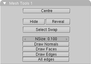
Top to bottom:
4.6.1.4.1. Centre
Moves the vertices altogether so that their barycenter is set to the Object center.
4.6.1.4.2. Hide
All selected vertices are temporarily hidden (HKEY).
4.6.1.4.3. Reveal
This undoes the Hide option (ALT-H).
4.6.1.4.4. Select Swap
Toggle the selection status of all vertices.
4.6.1.4.5. NSize
The length of the face normals, if they have been drawn.
4.6.1.4.6. Draw Normals
Indicates that the face normals must be drawn in EditMode.
4.6.1.4.7. Draw Faces
Indicates that the face must be drawn (as shaded blue/purple) in EditMode.
4.6.1.4.8. Draw Edges
Indicates that the selected edges must be highlighted. Partially selected edges (one vertex only selected) have a color gradient.
4.6.1.4.9. AllEdges
After leaving EditMode, all edges are drawn normally, without optimization.
4.6.2. Curve and Surface objects
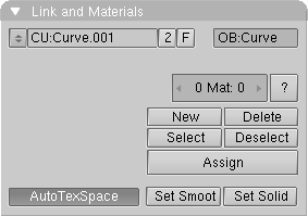
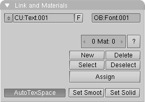
4.6.2.1. Link and Materials Panel
On the first line:
4.6.2.1.1. Curve Menu
Selects which Curve DataBlock is linked to this Object.
4.6.2.1.2. CU:
Shows Curve DataBlock name, allowing for changes.
4.6.2.1.3. F
Fake User button, to keep Mesh DataBlock even if unlinked.
4.6.2.1.5. AutoTexSpace
This option calculates the texture area automatically, after leaving EditMode. You can also specify a texture area yourself (Outside EditMode, in the 3D Window; TKEY), in which case this option is turned OFF.
On the right column there are the Material link buttons, whose behaviour is identical to that for a Mesh. Only difference is that they apply to Handles rather than vertices.
4.6.2.2. Curves and Surfaces Panel
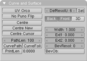
This panels owns two columns of buttons for curves, just one for surfaces; on the left:
4.6.2.2.1. UV Orco
UV Orco makes Blender calculating an undeformed Curve/Surface to be used as reference for "Orco" texture coordinates
4.6.2.2.2. No Puno Flip (Only Surfaces)
Blender renders by default double sided faces. That means you don't have to worry while modeling which directions normals point for faces. However, this can cause errors in calculating the vertex normals. This option forces Blender to calculate vertex normals without automatically flipping a face normal in the "right" direction while rendering. It is apparent with models with very irregular faces, which you still like to render Smooth using vertex normals.
4.6.2.2.3. Centre
Each ObData has its own local 3D space. The null point of this space is placed ed at the Object centre. This option calculates a new, centred null point in the ObData. This may change texture coordinates.
4.6.2.2.4. Centre New
As above, but now the Object is placed in such a way that the ObData appears to remain in the same place.
4.6.2.2.5. Centre Cursor
The new null point of the object is the 3D-Cursor location.
The following buttons are present only for Curve Objects:
4.6.2.2.6. PathLen
The length of the Curve path in frames, if there is no Speed Ipo.
4.6.2.2.7. CurvePath
Specifies that the Curve becomes a path. Children of this Curve now move over the curve. All Curves can become a path, but a 5th order Nurbs curve works best. It has no problems with movement and rotation discontinuity. This is an alternate to a Follow Path constraint
4.6.2.2.8. CurveFollow
The Curve path passes a rotation to the Child Objects. The 'Tracking' buttons determine which axis the path follows. In EditMode, horizontal lines are also drawn for a 3D curve. This determines the tilt, which is an extra axis rotation of the Child Objects. The tilt can be changed using the TKEY. Curve paths cannot give uniform perpendicular (aligned with the local Z axis) rotations. In that case, the 'up' axis cannot be determined.
4.6.2.2.9. PrintLen
The length of the path is printed in Blender units.
On the second column, again present only for Curves:
4.6.2.2.10. DefResolU
The standard resolution in the U direction for curves.
4.6.2.2.11. Set
Assigns the value of DefResolU to all selected curves.
4.6.2.2.12. Back
Specifies that the back side of (extruded) 2D curves should be filled.
4.6.2.2.13. Front
Specifies that the front side of (extruded) 2D curves should be filled.
4.6.2.2.14. 3D
The curve may now have vertices on each 3D coordinate; the front and back side are never rendered.
4.6.2.2.15. Width
The interpolated points of a curve can be moved farther apart or brought closer together.
4.6.2.2.16. Ext1
The depth of the extrude.
4.6.2.2.17. Ext2
The depth of the standard bevel.
4.6.2.2.18. BevResol
The resolution of the standard bevel; the bevel eventually becomes a quarter circle.
4.6.2.2.19. BevOb
The "bevel" Object. Fill in the name of another Curve Object; this now forms the bevel. For each interpolated point on the curve, the "bevel Object" is, as it were, extruded and rotated. With this method, for example, you can create the rails of a roller coaster with a 3D curve as the base and two small squares as bevels. Set the values ResolU of both Curves carefully, given that this bevelling can generate many faces.
4.6.2.3. Curve Tools Panel
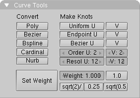
This Panel again shows Buttons which may or may not be there, according to the type of Object, curve or Surface.
Top to bottom, left to right:
4.6.2.3.1. Poly (Bezier Curve only)
A polygon only gives a linear interpolation of vertices.
4.6.2.3.2. Bezier (Bezier Curve only)
Vertices in a Bezier curve are grouped in threes; the handles. The most frequently used curve type for creating letters or logos.
4.6.2.3.3. Bspline
To be implemented
4.6.2.3.4. Cardinal
To be implemented
4.6.2.3.6. Uniform U, V
Sets the knots to create a uniform distribution. Use this for closed curves or surfaces (Here an in the following U applies to curves and both applies to surfaces).
4.6.2.3.7. Endpoint U, V
Sets the knots so that the first and last handles are always included.
4.6.2.3.8. Bezier U, V
Sets the knots table in such a way that the NURBS behave like a Bezier.
4.6.2.3.9. Order U, V
The order is the 'depth' of the curve calculation. Order '1' is a point, order '2' is linear, order '3' is quadratic, etc. Always use order '5' for Curve paths. Order '5' behaves fluently under all circumstances, without annoying discontinuity in the movement.
4.6.2.3.10. Resol U, V
The resolution in which the interpolation occurs; the number of points that must be generated between two vertices in the curve.
4.6.2.3.11. Set Weight
Nurbs curves have a 'weight' per handle; the extent to which a handle participates in the interpolation. This button assigns the Weight value to all selected vertices.
4.6.2.3.12. Weight
The weight that is assigned with Set Weight.
4.6.2.3.13. 1.0, sqrt(2)/4, 0.25, sqrt(0.5)
A number of pre-sets that can be used to create pure circles and spheres.
4.6.2.4. Curve Tools 1 Panel
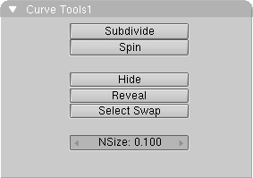
This Panel again shows Buttons which might or might not be there, according to the type of Object, curve or Surface.
Top to bottom:
4.6.2.4.1. Subdivide
Create new handle in curves, between selected ones.
4.6.2.4.2. Spin (Curves of Surface type only)
Spins the Curve around the cursor to create a surface. A whole 360 degree spin is performed.
4.6.2.4.3. Hide
All selected handles are temporarily hidden (HKEY).
4.6.2.4.4. Reveal
This undoes the Hide option (ALT-H).
4.6.2.4.5. Select Swap
Toggle the selection status of all handles.
4.6.2.4.6. NSize
This determines the length of the 'tilt' lines in 3DCurves.
4.6.3. Text objects
4.6.3.2. Curves and Surfaces Panel

This panels, again, shows the same items as for a (B�zier) Curve Object.
4.6.3.3. Font Panel
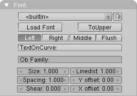
This Panel is Font specific, Top to bottom:
4.6.3.3.1. Font Menu
Allows to choose between available (loaded) fonts.
4.6.3.3.2. Pack Button
Embeds/de-embeds the font into/from the current .blend file.
4.6.3.3.3. Load Font
Turns nearest largest window into a File Select Window and you allows to select a True Type or PostScript font from the disk.
4.6.3.3.4. ToUpper
In EditMode, changes all letters into capitals or, if there are no small letters, changes all capitals to small letters.
4.6.3.3.5. Left, Right, Middle, Flush
All text is left, right, middle or flush-aligned.
4.6.3.3.6. TextOnCurve
Enter the name of a Curve Object here; this now forms the line along which the text is placed.
4.6.3.3.7. Ob Family
You can create fonts yourself within a Blender file. Each letter from this Font Object is then replaced by any Object you chose, and is automatically duplicated. This means that you can type with Objects! Objects to be considered as letters must belong to the same 'family'; they must have a name that corresponds to the other letter Objects and with the name that must be entered in this button. Important: set the option AnimButtons->DupliVerts ON! For example:
"Ob Family" = Weird.
The Objects that are to replace the letters a and b are called 'Weirda' and 'Weirdb', respectively.
4.6.3.3.8. Size
The letter size.
4.6.3.3.9. Linedist
The distance between two lines of text.
4.6.3.3.10. Spacing
The size of the space between two letters.
4.6.3.3.11. Shear
Changes the letters to italics.
4.6.3.3.12. Yoffset
This shifts the text up or down. For adjusting a "TextOnCurve".
4.6.3.3.13. Xoffset
This moves the text left or right. For adjusting "TextOnCurve".
4.6.4. Meta Objects
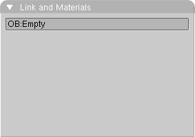
4.6.4.1. Link and Materials Panel
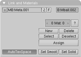
On the first line:
4.6.4.1.1. Meta Menu
Selects which Meta DataBlock is linked to this Object.
4.6.4.1.2. MB:
Shows Meta DataBlock name, allowing for changes.
4.6.4.1.3. F
Fake User button, to keep Mesh DataBlock even if unlinked.
4.6.4.1.5. AutoTexSpace
This option calculates the texture area automatically, after leaving EditMode. You can also specify a texture area yourself (Outside EditMode, in the 3D Window; TKEY), in which case this option is turned OFF.
On the right column there are the Material link buttons, which are still to be implemented, and the Smoothing buttons, not relevant to Meta Objects.
4.6.4.2. MetaBall Panel
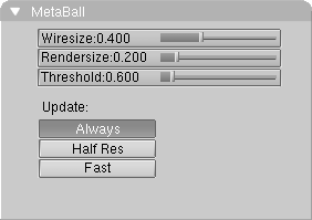
This panels is populated by buttons only if the base Meta Object is selected (the Meta object with a name without a trailing number). This is because these settings apply to all Meta Objects of the family.
4.6.4.2.1. Wiresize
The discretization step of the Meta Object in wireframe 3D Window, the larger the less accurate, but also the faster. Be careful with small values, as they use a lot of memory.
4.6.4.2.2. RenderSize
The resolution of the rendered MetaBall.
4.6.4.2.3. Threshold
This value determines the global 'stiffness' of the MetaBall.
4.6.4.2.4. Always, Half Res, Fast
In EditMode, the MetaBall is completely recalculated during transformations (Always); or rather calculated in half resolution (Half Res); or is only recalculated after the transformation is complete (Fast).
4.6.4.3. MetaBall Tools Panel
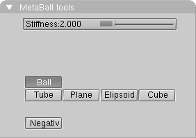
These are there only in EditMode and only if a Meta Object is selected. Top to bottom, left to right:
4.6.4.3.1. Stiffness
The stiffness can be specified separately on a per Meta Object basis.
4.6.4.3.2. Ball, Tube, Plane, Ellipsoid, Cube
The Meta Object type. You can change this after having created the Object.
4.6.4.3.3. Negative
The active 'ball' has a negative effect on the other balls.
4.6.6. Camera Objects
4.6.6.1. Link and Materials Panel
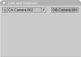
4.6.6.1.1. Camera Menu
Selects which Camera DataBlock is linked to this Object.
4.6.6.1.2. CA:
Shows Camera DataBlock name, allowing for changes.
4.6.6.1.3. F
Fake User button, to keep Mesh DataBlock even if unlinked.
4.6.6.1.4. OB:
Shows Object name, allowing for changes.
4.6.6.2. Camera Panel
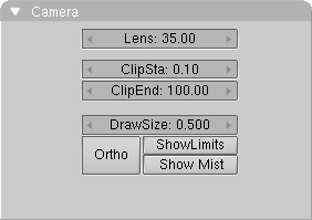
4.6.6.2.1. Lens
This number is derived from the lens values of a photo camera: '120' is telephoto, '50' is normal, '28' is wide angle.
4.6.6.2.2. ClipSta, ClipEnd
Everything that is visible from the Camera's point of view between these values is rendered. Try to keep these values close to one another, so that the Zbuffer functions optimally.
4.6.6.2.3. DrawSize
The size in which the Camera is drawn in the 3DWindow.
4.6.6.2.4. Ortho
A Camera can also render orthogonally. The distance from the Camera then has no effect on the size of the rendered objects.
4.6.6.2.5. ShowLimits
A line that indicates the values of ClipSta and ClipEnd is drawn in the 3Dwindow near the Camera.
4.6.6.2.6. ShowMist
A line that indicates the area of the 'mist' (see WorldButtons) is drawn near the Camera in the 3Dwindow.
4.6.7. Lamp Objects
4.6.7.1. Link and Materials Panel
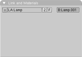
4.6.7.1.1. Lamp Menu
Selects which Lamp DataBlock is linked to this Object.
4.6.7.1.2. LA:
Shows Lamp DataBlock name, allowing for changes.
4.6.7.1.3. F
Fake User button, to keep Mesh DataBlock even if unlinked.
4.6.7.1.4. OB:
Shows Object name, allowing for changes.
4.6.8. Armature Objects
4.6.8.1. Link and Materials Panel
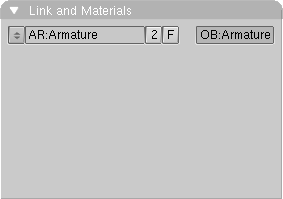
4.6.8.1.1. Armature Menu
Selects which Armature DataBlock is linked to this Object.
4.6.8.1.2. AR:
Shows Armature DataBlock name, allowing for changes.
4.6.8.1.3. F
Fake User button, to keep Mesh DataBlock even if unlinked.
4.6.8.1.4. OB:
Shows Object name, allowing for changes.
4.6.8.2. Armature Panel
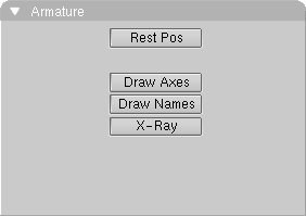
4.6.8.2.1. Rest Pos
Returns Armature to the original, rest, position for as long as it is 'on'.
4.6.8.2.2. Draw Axes
Draw Axes for all bones.
4.6.8.2.3. Draw Names
Draw Names for all bones.
4.6.8.2.4. X-Ray
Draw armatures in front of objects, to prevent armatures being hidden by meshes in Shaded mode.
4.6.8.3. Armature Bones Panel
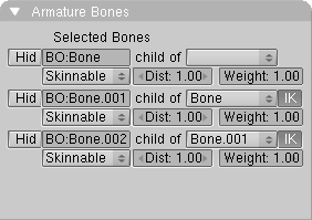
If Armature is in EditMode this panel appears, it is populated by a couple of lines for each Bone which is selected. Lines contain:
4.6.8.3.1. Hide
Toggle visibility of the Bone out of EditMode.
4.6.8.3.2. BO:
Text Button containing the name of the bone, and allowing its editing.
4.6.8.3.3. child of Menu
This Menu Button allows you to select any of the Bones in the armature which can be a parent of current bone, as the parent. A Bone can be set as an orphan by selecting the empty menu entry.
4.6.8.3.4. IK
Toggles Inverse Kinematics calculation from this bone up to its Parent on or off. An IK chain always stays continuous.
4.6.8.3.5. Skin Menu
Sets bone to Skinnable or Unskinnable for Vertex Group creating purposes. All other entries in the menu are under development and do not work right now.
4.6.8.3.6. Dist
Bone deformation distance, for automatic skinning (deprecated).
4.6.8.3.7. Weight
Bone deformation weight, for automatic skinning (deprecated).
4.6.9. Lattice Objects
4.6.9.1. Link and Materials Panel
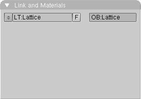
4.6.9.1.1. Lattice Menu
Selects which Lattice DataBlock is linked to this Object.
4.6.9.1.2. LT:
Shows Lattice DataBlock name, allowing for changes.
4.6.9.1.3. F
Fake User button, to keep Mesh DataBlock even if unlinked.
4.6.9.1.4. OB:
Shows Object name, allowing for changes.
4.6.9.2. Lattice Panel
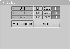
4.6.9.2.1. U, V, W
The three dimensions of the Lattice. If a new value is entered here, Lattice is placed in a regular, standard position.
4.6.9.2.2. Lin, Card, B
The manner in which the deformation is calculated can be specified dimension of the Lattice. The options are: Linear Cardinal spline and B spline. The last option gives the most fluid deformation.
4.6.9.2.3. Make Regular
This option sets the Lattice in a regular, standard position.
4.6.9.2.4. Outside
This type Lattice only displays vertices on the outside. The inner vertices are interpolated linearly. This makes working with large Lattices simpler.
4.6.10. Face select and Paint Modes
If the Object, in ObjectMode, has face/vertices there are additional modes available. The Face Select mode allows for individual face selection, most useful in UV texturing, while Vertex Paint and Weight Paint Modes allow you to handle vertex colors and weights of deformation groups. Texture Paint Mode allows you to paint the Object Image Textures on the 3D Viewport rather than on the Image Window.
4.6.10.1. Texture Face Panel
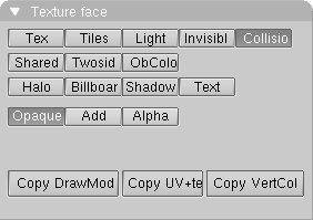
This panel exists only in Face Select Mode. Left to right and top to bottom:
4.6.10.1.1. Tex
Faces with this attribute are rendered textured in the textured view and the realtime engine. If no texture is assigned to the face it will be rendered in a bright purple.
4.6.10.1.2. Tiles
Images can have a tile-mode assigned. In the ImageWindow header you can indicate how many tiles an Image will be subdivided into. This button tells Blender to use this tilemode for the active face.
4.6.10.1.3. Light
The faces with this attribute are calculated with light in the realtime engine and the shaded views.
4.6.10.1.4. Invisible
This attribute makes faces invisible.
4.6.10.1.5. Collision
Faces with this attribute are taken into account for the real-time collision detection.
4.6.10.1.6. Shared
In Blender vertex colors are stored in each Face, thus allowing a different color for individual faces without having to add vertices. With this option, you can make sure that vertex colors are blended across faces if they share vertices.
4.6.10.1.7. Twoside
Faces with this attribute are rendered two-sided.
4.6.10.1.8. ObColor
Each Object in Blender has an RGB color that can be animated with Ipo-curves. With this option the realtime engine uses this ObColor instead of the vertex colors.
4.6.10.1.9. Halo
The faces are rendered as halos, which means the normals always point to the camera.
4.6.10.1.10. Shadow
Faces with this option set acting as shadow in the realtime-engine. In fact the face 'drops' on the floor. So you have to make sure the normal of the face points to the Z-axis. The face has to be located in the center of the Object (or slightly above). Best effect gives a texture with an alpha channel.
4.6.10.1.11. Opaque
The color of the textured face is normally rendered as color.
4.6.10.1.12. Add
This option makes the face being rendered transparent. The color of the face is added to what has already being drawn, thus achieving a bright 'lightbeam'-like effect. Black areas in the texture are transparent, white is full bright.
4.6.10.1.13. Alpha
Depending on the alpha channel of the image texture, the polygon is rendered transparent.
To copy the drawmodes from the active to the selected faces use the bottom line of Buttons.
4.6.10.1.14. Copy DrawMode
Copy the drawmode.
4.6.10.1.15. Copy UV+tex
Copies UV information and textures.
4.6.10.1.16. Copy VertCol
Copies the vertex colors.
4.6.10.2. Paint Panel
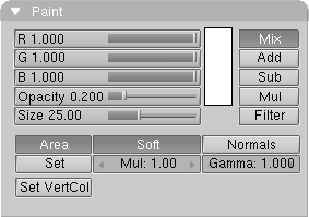
This panel exists in all Paint Modes, with different meanings.
In Vertex Paint Mode color is applied to vertices as a Vertex Color.
In Weight Paint Mode no color is applied, rather a weight to the currently selected Vertex Group for bone deformations. The amount of weight to be painted is specified in the Weight Num Button in the Link and Materials Panel.
In Texture Paint Mode the Image Texture of the current object is painted, just as you can do on an Image Editor Window, but with the texture wrapped rather than planar.
Top to bottom and left to right:
4.6.10.2.1. R, G, B
The active color used for painting (Vertex Paint and Texture Paint only)
4.6.10.2.2. Opacity
The extent to which the vertex colour changes while you are painting.
4.6.10.2.3. Size
The size of the brush, which is drawn as a circle during painting.
On the right column, beside a box showing the color itself:
4.6.10.2.4. Mix
The manner in which the new colour replaces the old when painting: the colours are mixed.
4.6.10.2.5. Add
The colours are added.
4.6.10.2.6. Sub
The paint colour is subtracted from the vertex colour.
4.6.10.2.7. Mul
The paint colour is multiplied by the vertex colour.
4.6.10.2.8. Filter
The colours of the vertices of the painted face are mixed together, with an "alpha" factor.
The bottom lines:
4.6.10.2.9. Area
In the back buffer, Blender creates an image of the painted Mesh, assigning each face a colour number. This allows the software to quickly see what faces are being painted. Then, the software calculates how much of the face the brush covers, for the degree to which paint is being applied. You can set this calculation with the option Area.
4.6.10.2.10. Soft
This specifies that the extent to which the vertices lie within the brush also determine the brush's effect.
4.6.10.2.11. Normals
The vertex normal (helps) determine the extent of painting. This causes an effect as if painting with light.
4.6.10.2.12. Set
The Mul and Gamma factors are applied to the vertex colours of the Mesh.
4.6.10.2.13. Mul
The number by which the vertex colours can be multiplied.
4.6.10.2.14. Gamma
The number by which the clarity of the vertex colours can be changed.
4.6.10.2.15. Set VertCol
Set vertex color of selection to current.